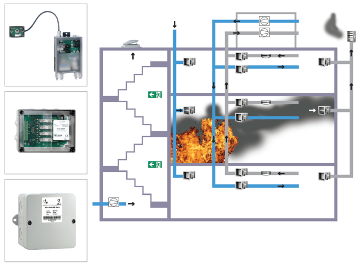
Fire damper is fitted where the duct penetrates the lobby enclosure.
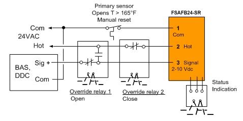
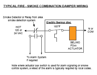
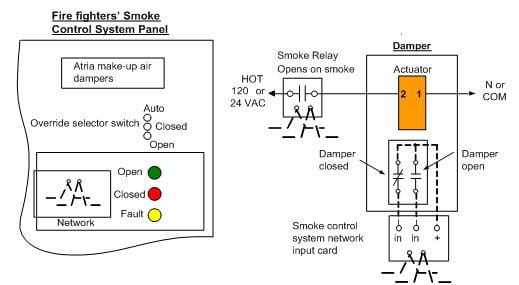
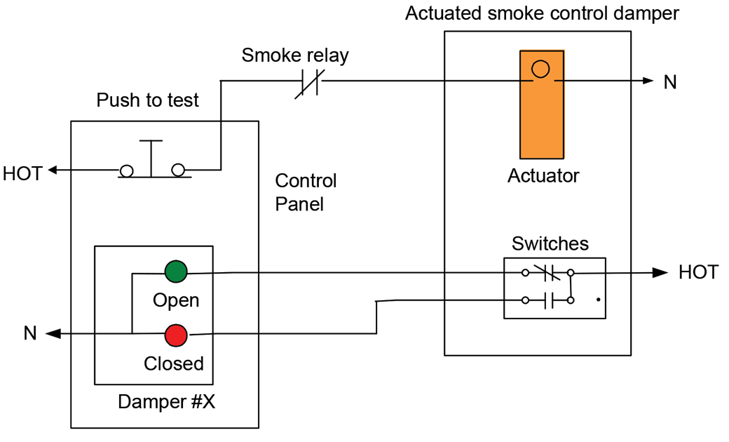
Fire smoke damper wiring.
Figure 2 smoke detector and combination fire and smoke damper wiring.
Fire smoke damper installation allows you in balancing and monitoring the airflow in every single room.
A wiring diagram is a streamlined conventional pictorial depiction of an electrical circuit.
Fire smoke damper installation keeps the humidity of an area under control.
It shows the elements of the circuit as simplified shapes and also the power and also signal connections between the devices.
Fire smoke damper wiring diagram exactly what s wiring diagram.
Diagram 7 1 1 e 3 the omission of fire damper to the duct where it penetrates the lobby enclosure is acceptable if a masonry slab is constructed below the duct to act as compartment ceiling.
About 20 are installed in more customized applications that are designed by the fire protection and mechanical engineers.
Collection of fire smoke damper wiring diagram.
The advanced fire smoke dampers come with the climate control feature so that the inhabitants of a building can stay comfortably irrespective of the outside temperature.
Variety of fire smoke damper wiring diagram.
All fire smoke dampers must be installed in a sleeve.
Should a fire penetrates the fire damper it still be contained within the duct.
It shows the components of the circuit as streamlined shapes and also the power as well as signal connections in between the gadgets.
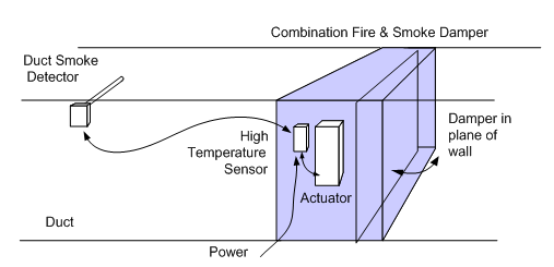
Combination fire and smoke dampers.
Installation and maintenance to ensure optimum operation and performance the damper must be installed so it is square and free from racking.
A wiring diagram is a sort of schematic which uses abstract photographic icons to show all the interconnections of elements in a system.
Iom fire smoke dampers 0718 nca manufacturing inc.
A wiring diagram is a streamlined conventional photographic depiction of an electrical circuit.
A wiring diagram is a streamlined standard photographic depiction of an electric circuit.
Variety of fire smoke damper wiring diagram.
It reveals the components of the circuit as simplified shapes as well as the power as well as signal links between the tools.